Thrust Vector Control - Final Project
Blas Kozicki
Idea
Modern rockets don't have fins but they still manage to point up and remain stable during ascent but, how? The answer is Thrust Vector Control, or TVC for short. TVC is a system that with the help of a gimbal, rotates an engine on two axis, pitch and yaw.
While I don't have the time, the experience, nor the resources to build a real TVC system, there is a very interesting "field" called Model Rockets. Model Rockets are small hobbyist rockets that can actually fly (sometimes REALLY high!) thanks to small-scale solid rocket engines. There are many companies that sell them, such as Estes or AeroTech. My goal is therefore to build a Thrust Vector Control system/mount in a model-rocket scale, hopefully before the end of the class.
Before getting started, we need to define the base size parameters for our project. For that, we need to chose which motor we will hypotetically chose. We'll assume that the TVC system we create will be quite heavy (200 grams or maybe even more), you will understand why when we discuss the different components we need. Medium to large engines have a diameter of 24 mm according to Estes, so that is the measurement that we will build our TVC around.
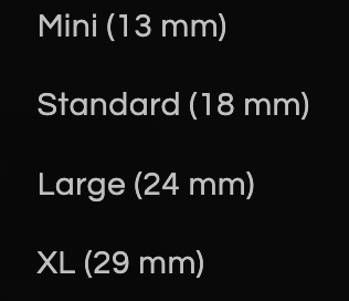
Different rocket sizes (Estes)
Components
We will divide our TVC into two separate main parts to make the designing process easier:
Gimbal
The gimbal is the part that will rotate the engine. It will be composed of two parts, the outer and the inner gimbal. The outer gimbal will rotate on the pitch(Y) axis, and the inner gimbal will rotate on the yaw (X) axis. The inner gimbal will be attached to the engine, and the outer gimbal will be attached to the rocket body. We will need one servo for each gimbal.
Electronics
To control all of our different electronics we will use an ESP32. The ESP32 is much more poweful than arduino, and this project needs high response times to accurately correct the trajectory of our rocket. The microcontroller needs to control two servos and read the data from a sensor, from which we will get the orientation of the rocket.
The sensor we are going to use is an MPU6050. I've worked with it in the past, and it's a very capable IMU.
BOM (bill of materials)
- ESP32
- 3D printing filament
- x2 Micro Servo
- Wires
- MPU6050
- Protoboard
- M2 & M3 Screws (many lengths)
- M2 & M3 Threaded inserts
Design
The first idea I had for the gimbal was a three circle design, in which the outer cercle is stationary (attached to the rocket) and the other two circles move in different axis. The sketch below illustrates the design I had in mind:
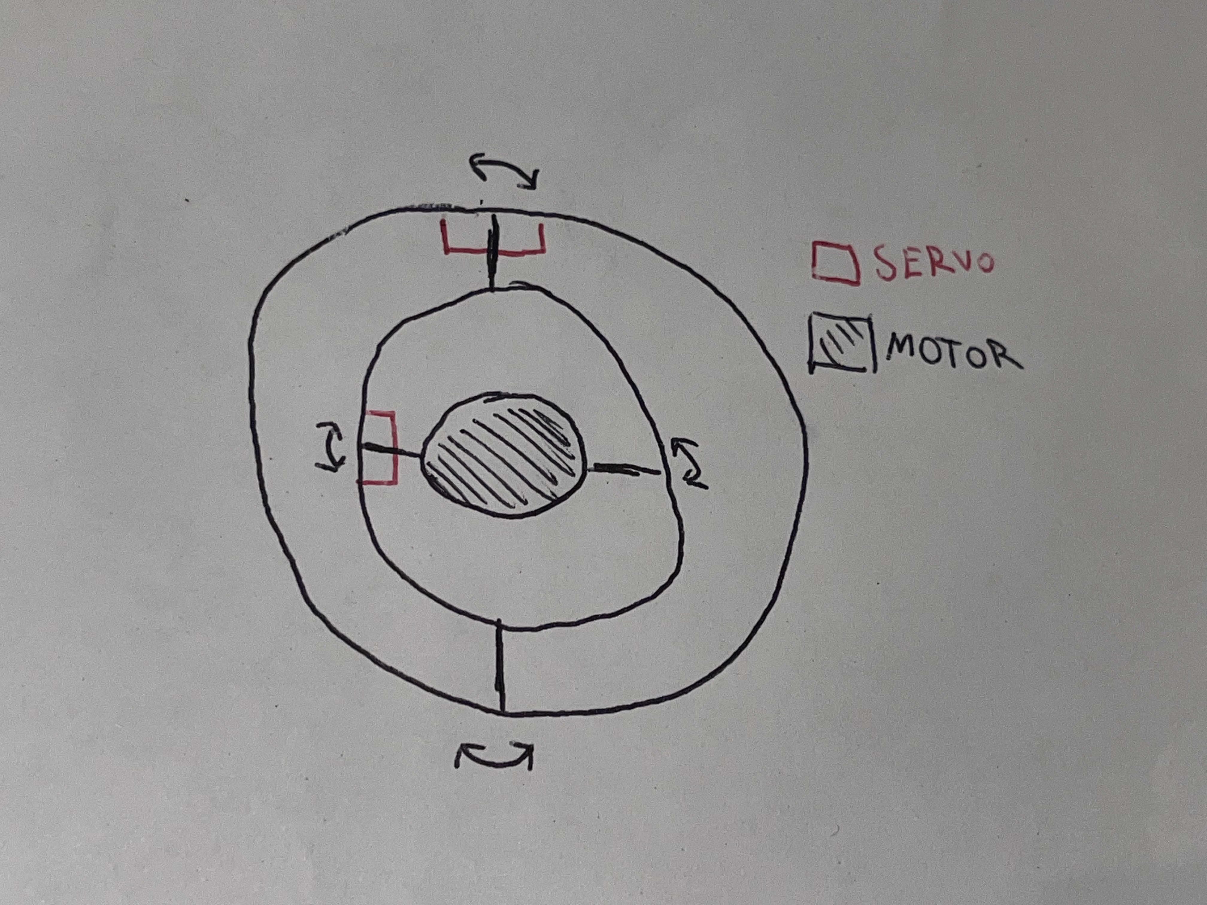
I quickly discarded this idea, as the diameter of the TVC would've ended up being really big in respect to the size of the motor, which is something unrealistic that could never fly.
I then started scouting the internet for ideas. Kassia (TA) suggested a very interesting mechanism called a Spherical Parallel Manipulator. As you can see in this video, the device has 3 degrees of rotational freedom, so it can also rotate in the roll axis. Our rocket only needs 2 degrees of freedom, and adding that third one adds quite a lot of challenges as you can see in the video, so this solution was too "advanced" for our needs. Then, I tried looking at people who had done TVC mounts before, to have an idea of what type of gimbal they used.
Thrust Vector Control Mount by Contradius
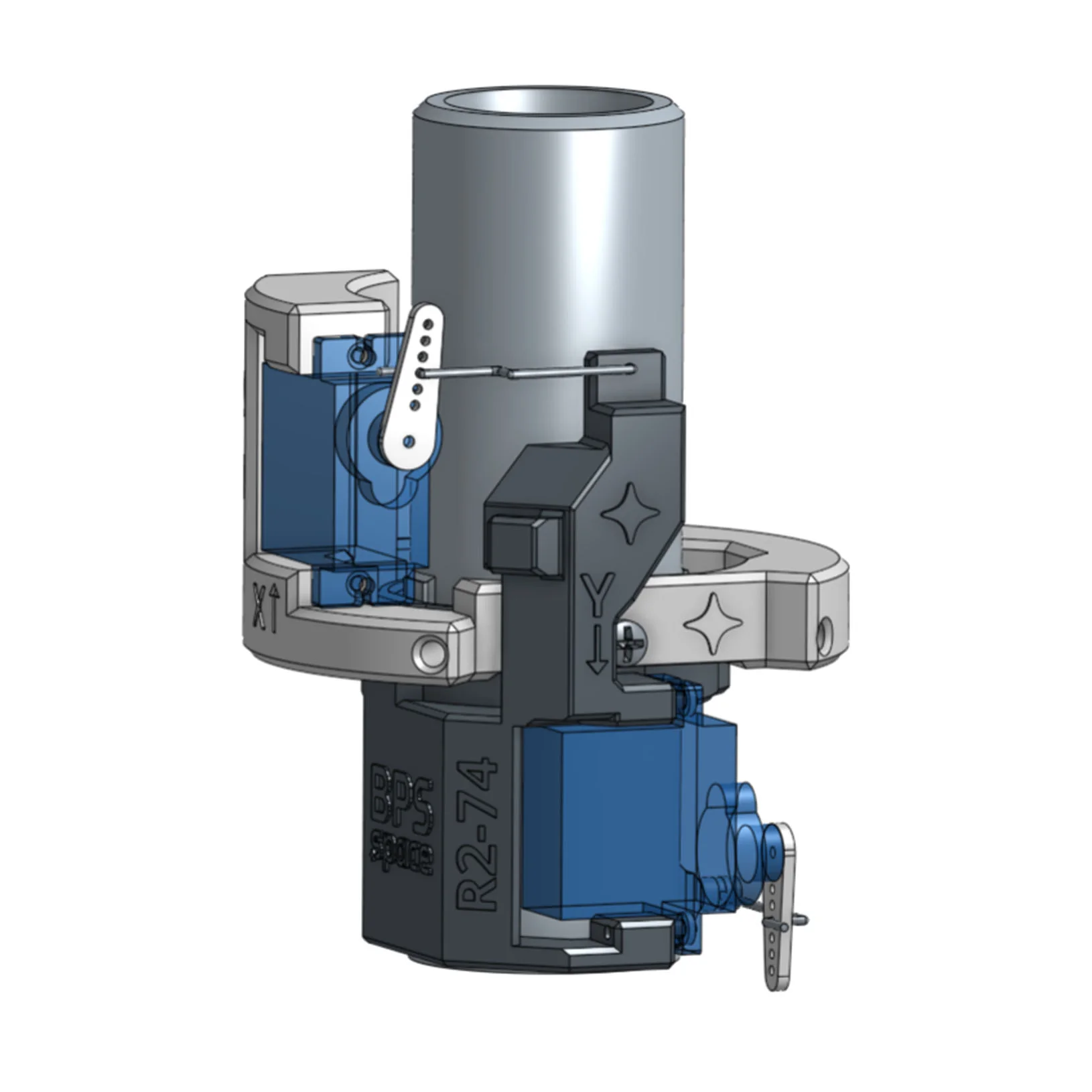
Thrust Vector Control mount by BPS.space
Both of the designs that I found were of great insipration, and gave me a really good idea of how I wanted to design my own TVC.
The last design choice I needed to make before starting modeling, was how to attach the different parts of the design. I found something called threaded inserts in lab. Threaded inserts are inserted into an object to add a threaded hole, and is ideal for 3D prints, as they can be inserted using only heat (coming from a soldering iron, for example). Below you will find an example from reddit of someone adding a threaded insert ot a 3D print.
Threaded Inserts in 3D Prints(make the walls twice as thick around the Insert ID)
by u/JJCCENG in 3Dprinting
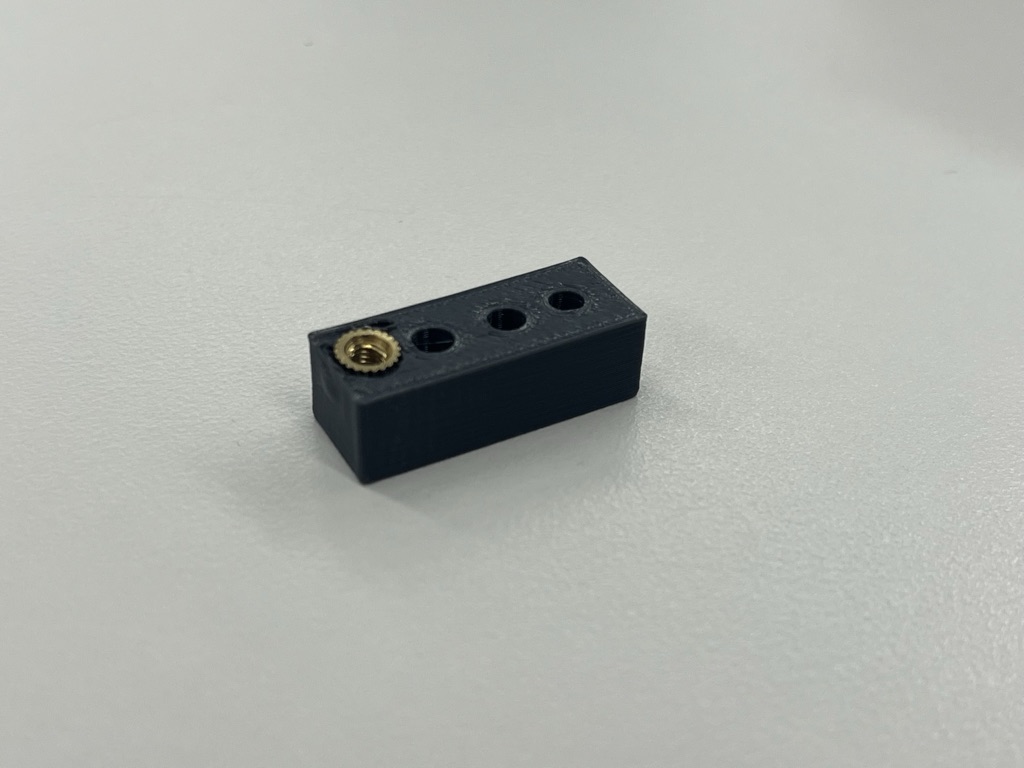
I knew that when modeling, the holes where the threaded inserts would be added needed to be slightly smaller than the actual size of the insert, but I did not know exactly how smaller. That is why I designed and 3D printed a small box with different sized holes to determined which worked the best for an M3 size insert. It turns out that the best hole diameter for M3 inserts is about 4.2 mm.
CAD Modeling
Modeling Micro Servos
To accurately design the TVC, we need to know the size of each component. To make modeling even easier, I decided to 3D model the micro servo motors so we can then insert them into the design.
I took various measurements using a caliper:
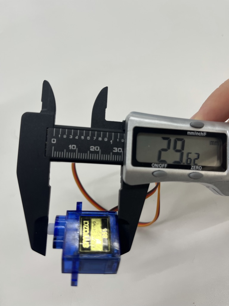
And ended up with the following design.
Modeling the Inner Gimbal
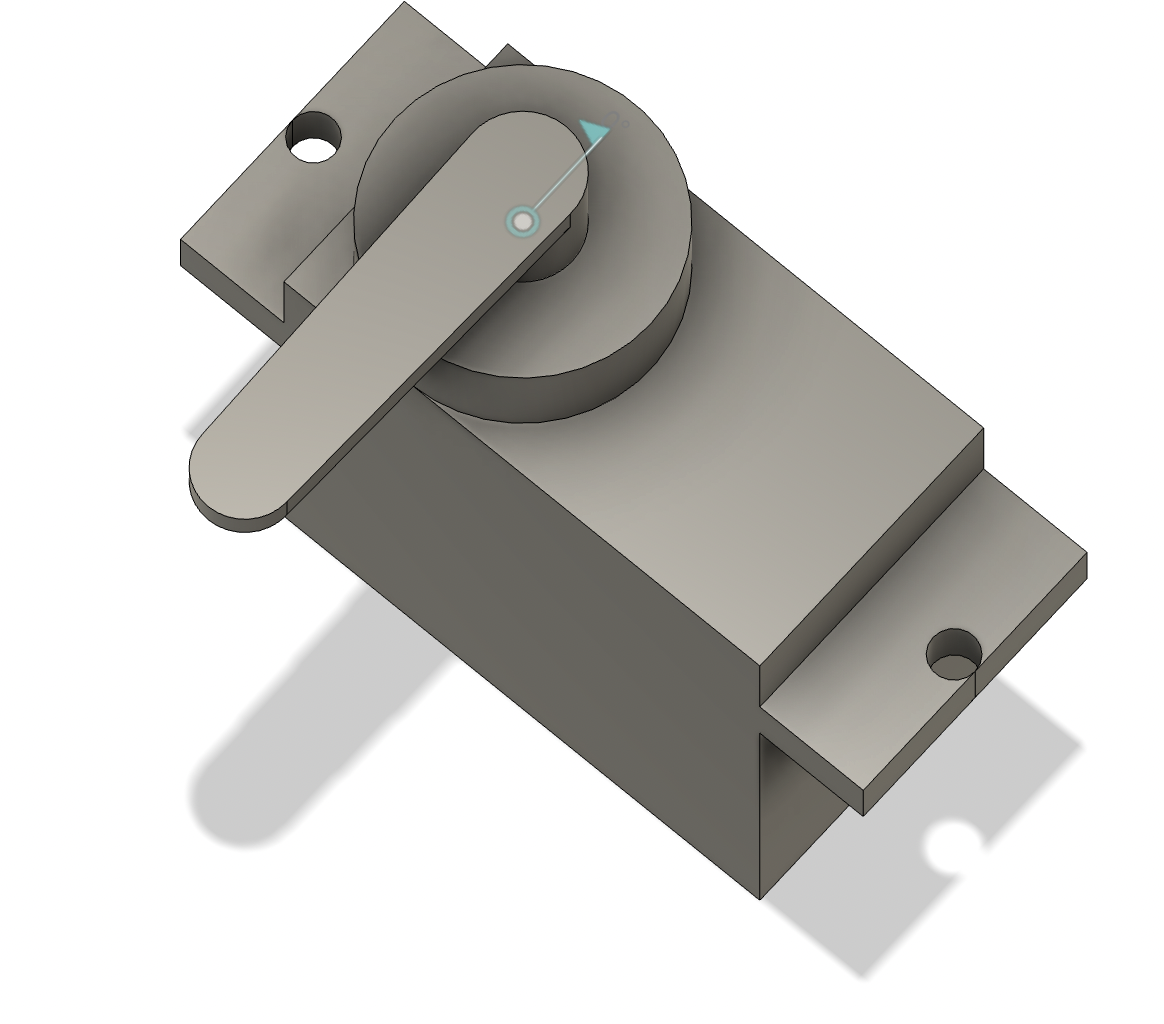
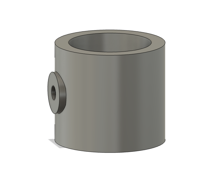
I had no idea how big the final diameter of the TVC would be, so I decided the best idea was going to be to start from the inside. I started by created a motor holder with a 24 mm inner diameter and 4 mm thick walls. I then added small surface where we will add a threaded insert, to attach the servo motor to the motor holder using a rod. The height of the holder will change depending on how tall the TVC ends up being, and the height in the image is not the same in the final revision.
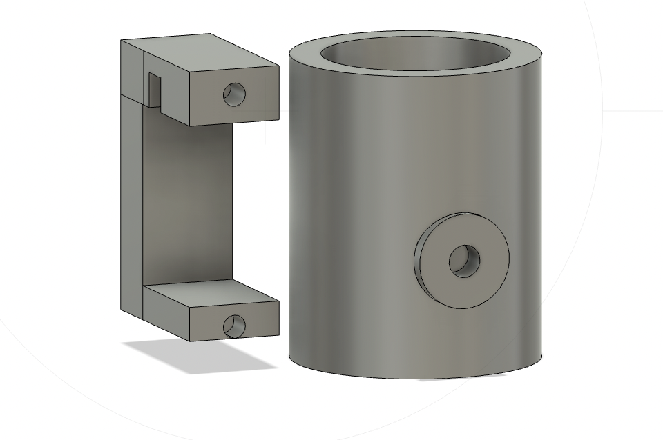
I added a holder for the micro servo that will be part of the inner gimbal. As you can see, it has 2 holes to add M2 threaded inserts (which is the size of the holes that the micro servo has), and a small opening on top for the wires to fit. As a fun fact, the first revision did not have that small hole, and as you can probably guess the micro servos did not fit at all (we do not really like to talk about that version!).
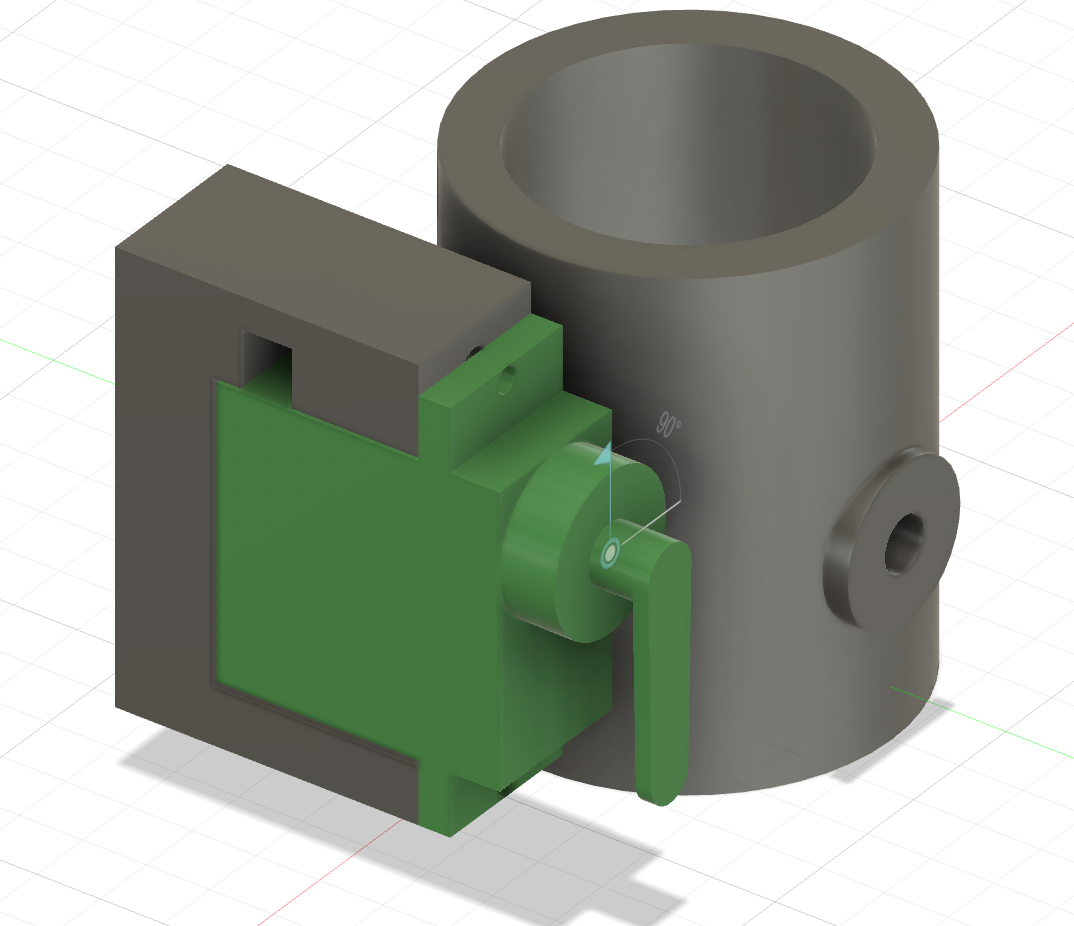
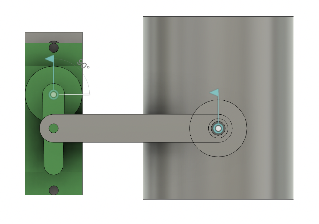
I then attached the the servo and motor holder using a 35 mm rod and some joints.
After that, I made the motor holder taller and built an eliptcal structure to contstrain the movement of the motor holder. I connected that to the servo holder we just built, and was left with the basic structure for the inner gimbal.
For the inner gimbal to hold the motor holder but at the same time allow it to rotate freely, I extruded two small cylinders from the motor holder, and cut a semi-circle on the inner gimbal, as you can see below.
Then, I made a small "cap", that would be screwed in place with 2 M2 screws and would hold everything in place. The whole thing was then mirrored ot the other side.
The last thing needed for the inner gimbal is an attach point for the rod that will be connected to the servo on the outer gimbal. To make it, I just extruded a small cube out of the top of the servo holder and added a hole for an M3 threaded insert.
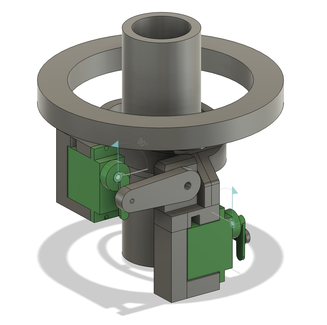
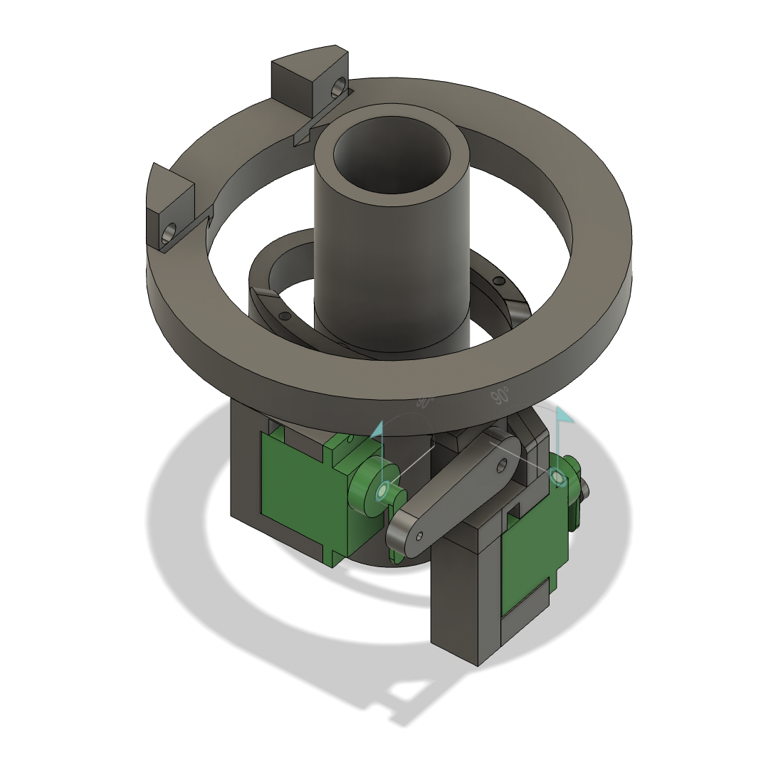
Modeling the Outer Gimbal
I started by duplicating the servo and its holder, and adding a rod to connect them to the inner gimbal. The rod in this case is thicker, as it does not only need to move the motor holder, but also the inner gimbal.
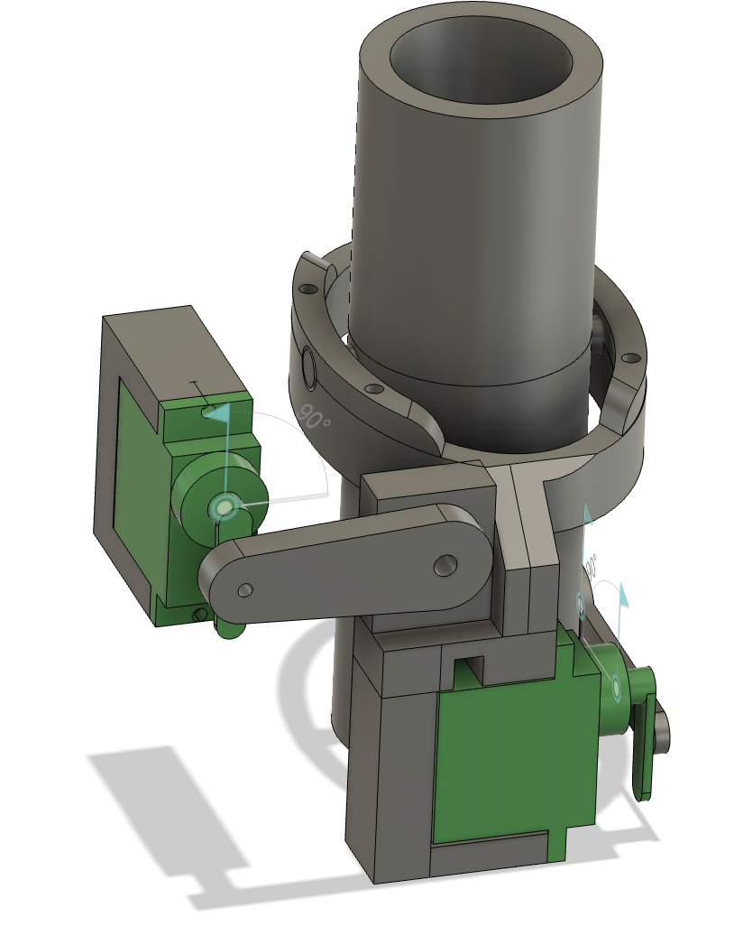
The next step was to finish the general shape of the whole outer gimbal, so I sketched and extruded a cercle on top of the outer servo holder.
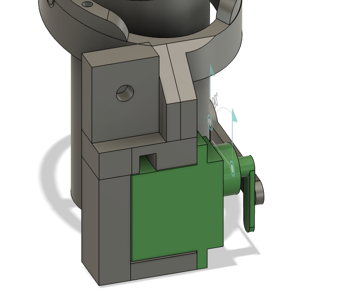
Finally, I added a slot for the protoboard to be attached to the TVC. The length of the protoboard was around 60.5 mm, but to make sure it fitted I made the slot 63.5 mm . The thickness was 1.5 mm, which I did not increase so the would not fall off the TVC. Additionally, I added a small extrusion with some holes where it is possible to add threaded inserts to attach the protoboard with screws, which is necessary if the thing is actually flown, but I found that for testing it is just better to press-fit it in place as it is easier to remove.
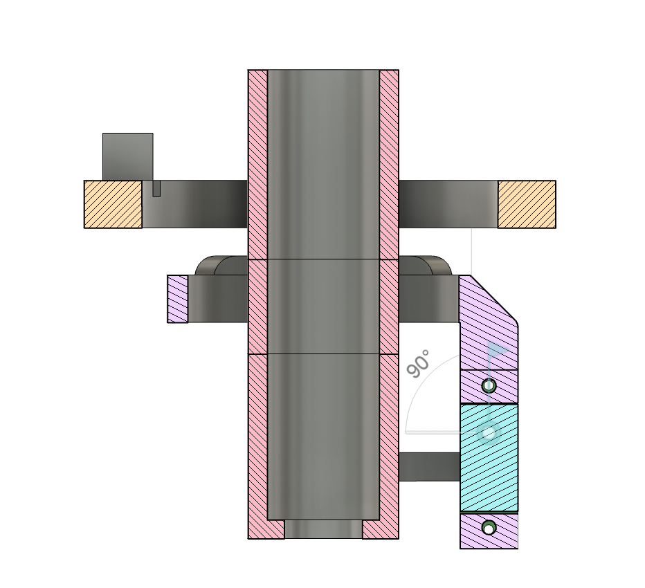
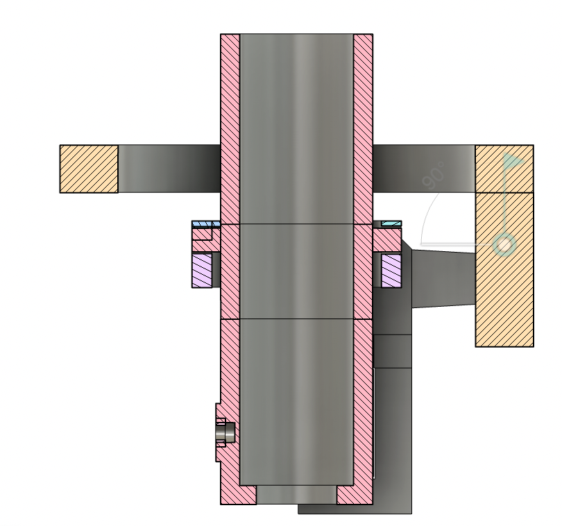
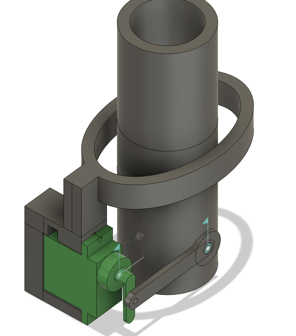
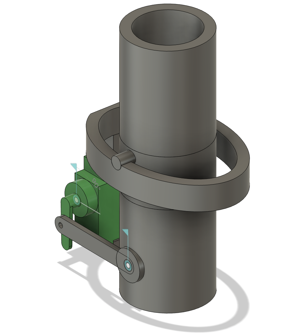
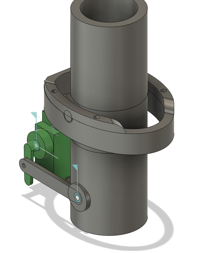
X axis cross section of finished TVC
Y axis cross section of finished TVC
You can take a look at the whole 3D model here, or you can download the files at the end of the page.
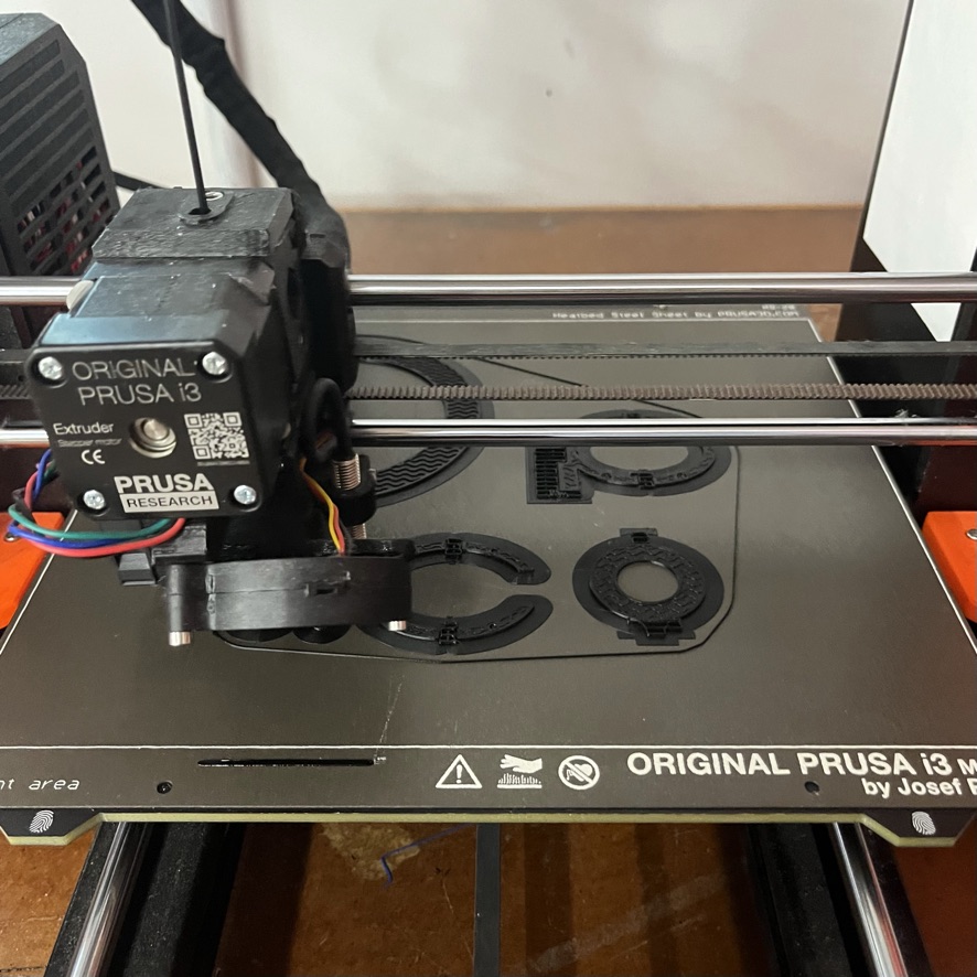
3D Printing
3D printing was pretty straightforward. I exported all the different parts of the design to Prusa Slicer, and oriented them in the best way possible. I obviously activated supports, and used a 20% infill to make sure the parts were strong. The whole print takes around 9 hours in a Prusa i3 MK3S+.
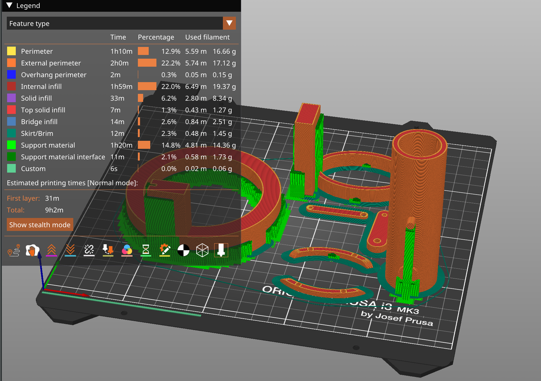
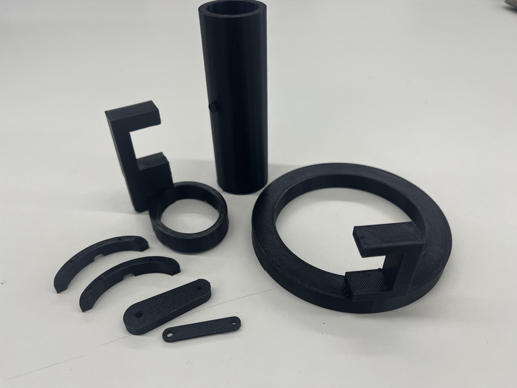
The color of the filament may be different in other images, as the TVC was printed several times.
Electronics
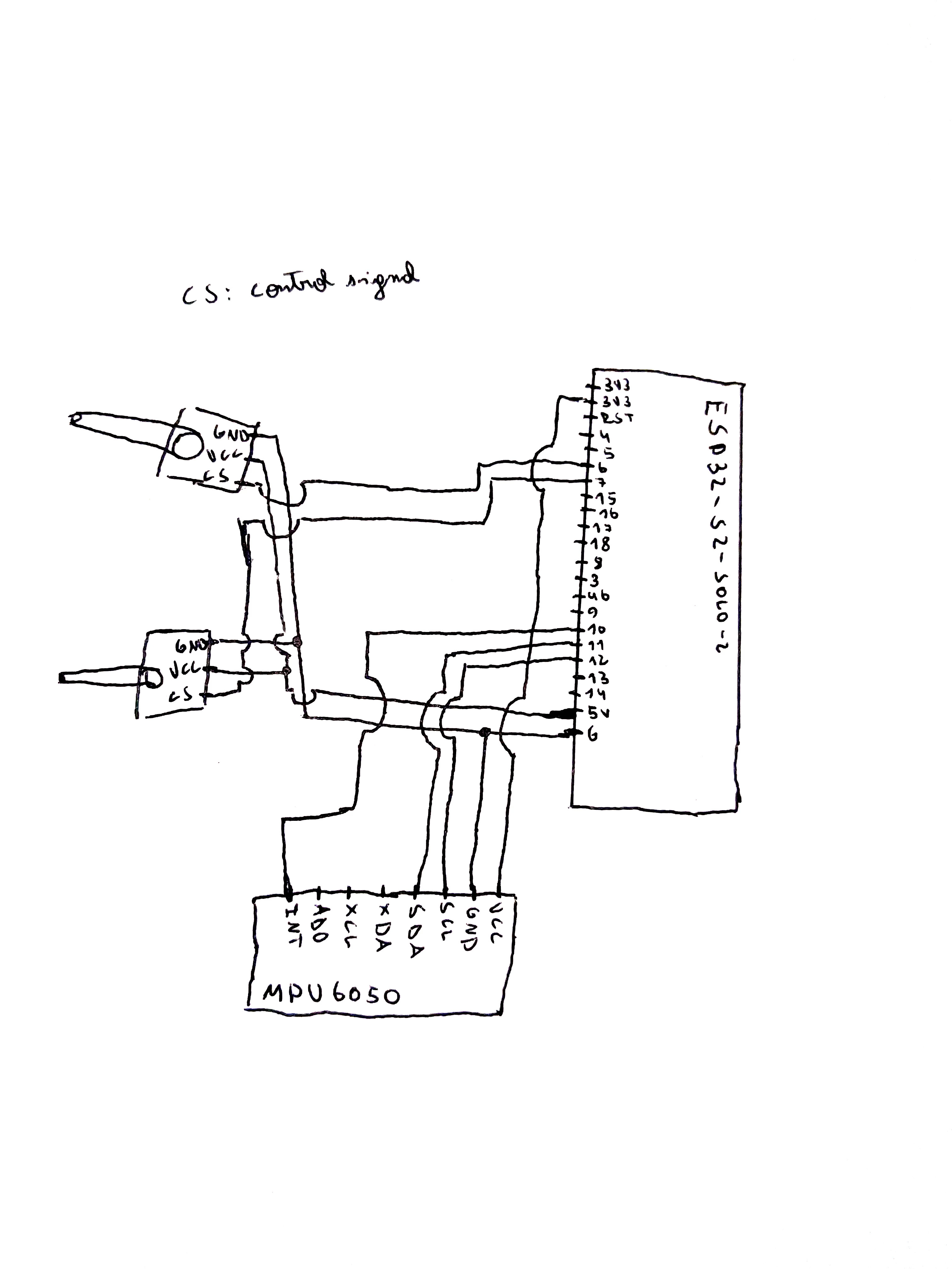
The elctronics were pretty simple. We need an ESP32, two servos, and an MPU6050. The ESP32 will be connected to the protoboard using header pins, so we can avoid soldering the ESP32 to the protoboard and leaving it there forever. the two servos will be connected to power and ground from the ESP32, and each of them to one PWM-capable pin. The MPU wiring was covered on Week 6.
The first thing I did was to draw a simple schematic (not my finest work, I have to admit):
I then wired everything up in a breadboard to make sure everything worked before upgrading to a "permanent" protoboard. The green connectors you can see are where the servos are connected.
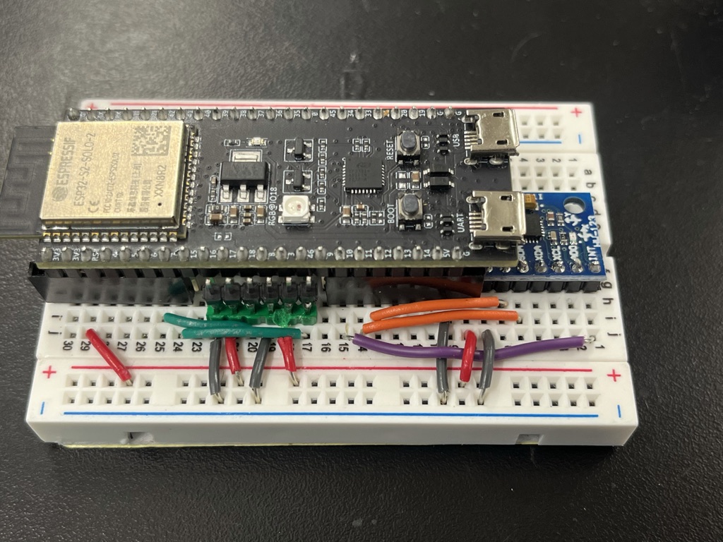
After testing everything with some very basic code that is not worth showing, I soldered everything.
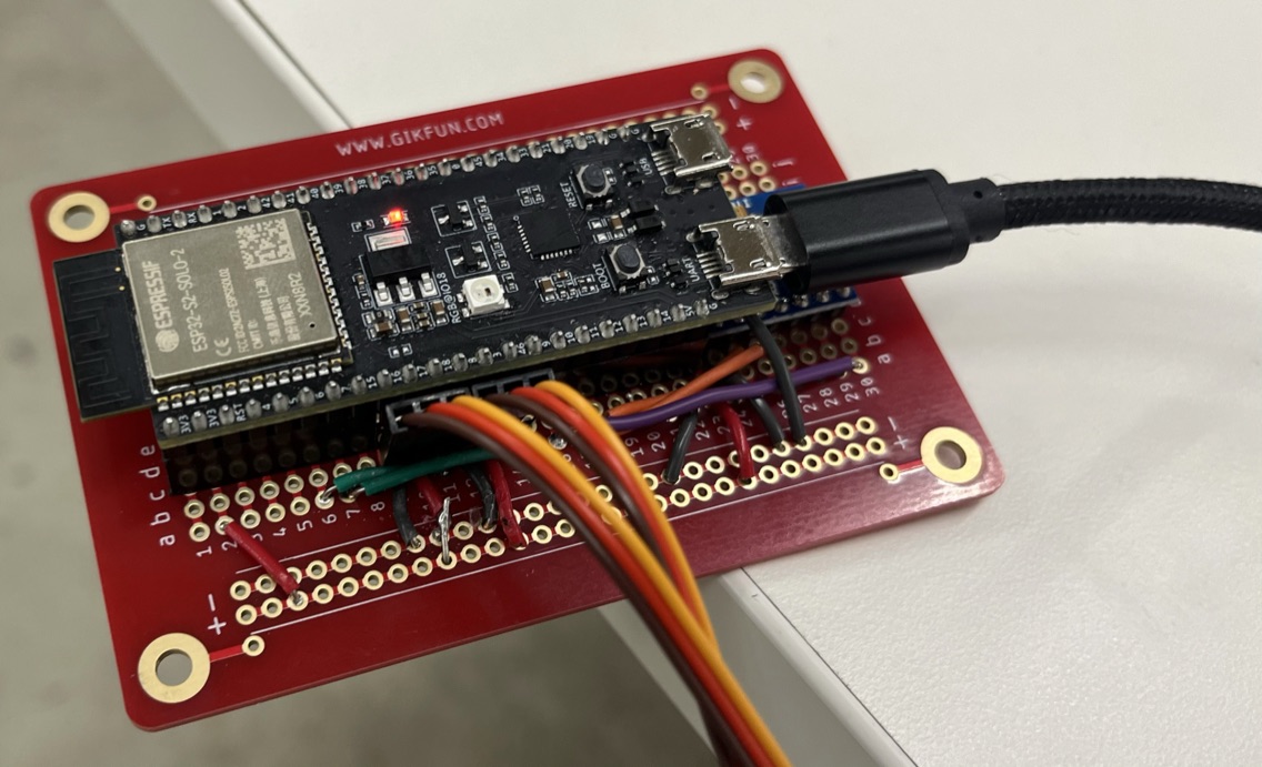
Assembly
The assembly process took way less than I anticipated. Adding the threaded inserts was quite easy, but on the other hand finding the appropiate screws was pretty difficult (you would be surprised by the different types of screws that the lab has).
Programming
The code I used to get the TVC to work is by no means complete, and is only a proof of concept. To get this TVC to fly flawlessly, I would need to tune a PID controller with the correct gains, and take into account the thrust curve of the motor. All these things are definitely possible, but take quite a lot of time, which I did not have. So for this MVP we will content ourselves by inversing the angle readings from the MPU6050 and clamping them to the clearances of the micro servos.
The first few lines include the libraries we'll be using, and define some basic variables. There are many "fifo" and "dmp" variables which are necessary to setup the MPU6050 library, so I wont be explaining what those are. The calibration values are basically angles I hand-picked by just sending different values to the servo and eye-balling a good limit, and are therefore not at all accurate. At the end of the page we will talk more about accuracy, but keep in mind we are using $4 servos, so the precision of our calibration doesn't really matter THAT much.
I then wrote a simple servo initialization function that attaches the servos to their pins, and then tests their full range of motion based on the calibration values we wrote earlier.
The setup function then begins serial communication, which is useful for debugging, and starts the I2C protocol to communicate with the MPU-6050. Then I use slightly modified code from the MPU6050 library examples to initialize the sensor and calibrate it.
The final part of the code is the loop function, which is what reads the orientation from the sensor and then moves the servos. The servos don't move instantly, so I added a .1 second "cooldown". I stored in some variables the yaw and pitch raw readings, the clamped values (clamped using the calibration values), and then the correction needed. All the weird "if else" logic you see is just a way to deal with negative and positive numbers, because the readings start at zero and can go to negative and positive values, but the servo angles start at 0, and can't be negative. That portion of the code can definitely be simplified and made more efficient, and is something I want to work on in the future.
Conclusion
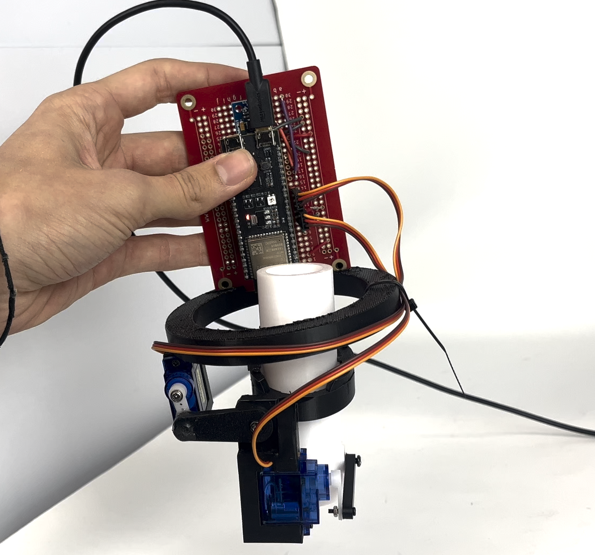
After some testing, I determined that the TVC worked really well, but is very incaccurate for a number of reasons. First, we are using really cheap and even obsolete electronic components. The micro servos are great for many small projects that don't require precision, which is not our case. They have a precision of around 3 degrees, or even more. On the other hand, the MPU6050 has a lot of noise and is even obsolete. There are many other more expensive choices that might be a good idea to get now that we have a basic TVC working, and I think that is the next step on this project. The TVC design can definitely be improved, by adding a contraint on the outer gimbal, so that the pivot of the rotation stops being the servo, that is off-centered, and works just like the inner gimbal. Those are just a few things that can be improved on this project, however, not everything is bad. We managed to get a basic Thrust Vector Control mount working in just a few weeks, and learned TONS of extremely useful and interesting things. Overall, I had lots of fun working on this project and will continue working on it (will probably add an URL here redirecting to a new page where I will post updates!).