Output devices, making things do things
18th July 2023
Choosing an output device
The first part of this week's assignment is to choose and use an output device using a microcontroller. My final project requires some way to show its status in realtime to the user, so I decided to try to use an RGB LED.
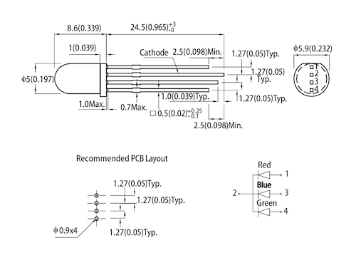
This image shows us that the longest leg is the common ground, the first leg corresponds to red, the third one to blue, and the fourth to green.
As many probably know, the color blue has a higher wavelength than red and green. This means the LED needs more energy to emit that color. This is why if we use the same resistance values for each color, you will notice that the blue will be a lot fainter than the red. I used a 1000 ohm resistor for the red and green leg (you could use a lower value for the green too, but I don't think it makes that much of a difference), and a 500 ohm resistor for the blue leg.
I wired everything up in the same breadboard I used in the previous assignment to be able to combine the MPU6050 and the RGB LED to make something interesting, but we'll get to that in a bit. After everything was wired, I set the pin where the RED leg was connected HIGH to see if it was working:
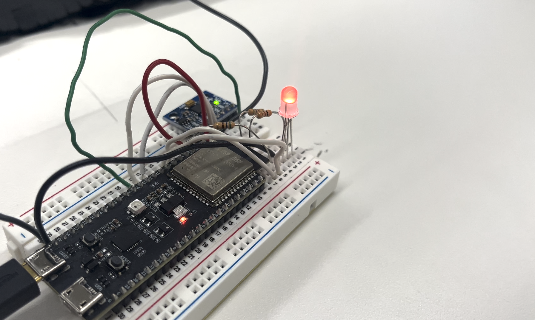
As you can see, the LED is working as expected. I then decided to try to make it change colors using 3 loops. The program goes through each possible value for blue (0-255), and then increments the green by one and does the blue loop all over again. When the green reaches 256, it goes back to 0 and red increases by one, starting the whole loop again. This technically goes through each possible color, but what I did not think about is the amount of possible colors we can "make" using an RGB light. Each channel (red, green, blue) can go from 0 to 255, so each has 256 possible values, if we do the math, it turns out that the total amount of combination equals 255^3 which is equal to 16,777,216. If we stayed in one color for 10 miliseconds before switching to the next one, it would take us 0.001 * 16777216 = 167772.16 seconds, or 46.6 hours to see every color. I do not intend to stare a tiny RGB Led for nearly 2 days with no breaks, so I was going to have to do something different.
I found some code online which had an array of "key" rainbow colors, so I modified for it to work with my setup and ran it:
Sped up video
#define redpin 4
#define greenpin 5
#define bluepin 6

const uint8_t lights[360] = {
  0, 0, 0, 0, 0, 1, 1, 2, 2, 3, 4, 5, 6, 7, 8, 9, 11, 12, 13, 15, 17, 18, 20, 22, 24, 26, 28, 30,
  32, 35, 37, 39, 42, 44, 47, 49, 52, 55, 58, 60, 63, 66, 69, 72, 75, 78, 81, 85, 88, 91, 94, 97,
  101, 104, 107, 111, 114, 117, 121, 124, 127, 131, 134, 137, 141, 144, 147, 150, 154, 157, 160,
  163, 167, 170, 173, 176, 179, 182, 185, 188, 191, 194, 197, 200, 202, 205, 208, 210, 213, 215,
  217, 220, 222, 224, 226, 229, 231, 232, 234, 236, 238, 239, 241, 242, 244, 245, 246, 248, 249,
  250, 251, 251, 252, 253, 253, 254, 254, 255, 255, 255, 255, 255, 255, 255, 254, 254, 253, 253,
  252, 251, 251, 250, 249, 248, 246, 245, 244, 242, 241, 239, 238, 236, 234, 232, 231, 229, 226,
  224, 222, 220, 217, 215, 213, 210, 208, 205, 202, 200, 197, 194, 191, 188, 185, 182, 179, 176,
  173, 170, 167, 163, 160, 157, 154, 150, 147, 144, 141, 137, 134, 131, 127, 124, 121, 117, 114,
  111, 107, 104, 101, 97, 94, 91, 88, 85, 81, 78, 75, 72, 69, 66, 63, 60, 58, 55, 52, 49, 47, 44,
  42, 39, 37, 35, 32, 30, 28, 26, 24, 22, 20, 18, 17, 15, 13, 12, 11, 9, 8, 7, 6, 5, 4, 3, 2, 2,
  1, 1, 0, 0, 0, 0, 0, 0, 0, 0, 0, 0, 0, 0, 0, 0, 0, 0, 0, 0, 0, 0, 0, 0, 0, 0, 0, 0, 0, 0, 0, 0,
  0, 0, 0, 0, 0, 0, 0, 0, 0, 0, 0, 0, 0, 0, 0, 0, 0, 0, 0, 0, 0, 0, 0, 0, 0, 0, 0, 0, 0, 0, 0, 0,
  0, 0, 0, 0, 0, 0, 0, 0, 0, 0, 0, 0, 0, 0, 0, 0, 0, 0, 0, 0, 0, 0, 0, 0, 0, 0, 0, 0, 0, 0, 0, 0,
  0, 0, 0, 0, 0, 0, 0, 0, 0, 0, 0, 0, 0, 0, 0, 0, 0, 0, 0, 0, 0, 0, 0, 0, 0, 0, 0, 0, 0, 0
};

int loopdelay = 100;
int displaylength = 40;

void setup() {
}

void loop() {
  for (int k = 0; k < 360; k++) {
    analogWrite(redpin, lights[(k + 120) % 360]);
    analogWrite(greenpin, lights[k]);
    analogWrite(bluepin, lights[(k + 240) % 360]);
    delay(displaylength);
  }
  delay(loopdelay);
}
Combining input and output
After playing around with the LED, I decided to use it to make something that is actually useful. I had the MPU6050 already wired, so I fixed upon an inclinometer, or tilt sensor. My idea was to make a device that turns green when is on a 0 degree angle (parallel to the floor), yellow when in a small angle, and red when very far from perfect. I had wired the input and output devices in the same breadboard, so all that was left to do was the software-side of the device.
I started by making a class to control the rgb led, and then used the code from the last post to get the angle. Here is the full program:
#include "Wire.h"
#include "MPU6050_6Axis_MotionApps20.h"

class rgbLED {
private:
  byte redPin;
  byte bluePin;
  byte greenPin;

public:
  rgbLED(byte _redPin, byte _greenPin, byte _bluePin) {
    redPin = _redPin;
    bluePin = _bluePin;
    greenPin = _greenPin;
  }

  void color(int red, int green, int blue) {
    analogWrite(redPin, red);
    analogWrite(greenPin, green);
    analogWrite(bluePin, blue);
  }
};

MPU6050 mpu;

#define INTERRUPT_PIN 18
#define I2C_SDA_PIN 16
#define I2C_SCL_PIN 17

rgbLED led(4, 5, 6);

bool dmpReady = false;   // set true if DMP init was successful
uint8_t mpuIntStatus;    // holds actual interrupt status byte from MPU
uint8_t devStatus;       // return status after each device operation (0 = success, !0 = error)
uint16_t packetSize;     // expected DMP packet size (default is 42 bytes)
uint16_t fifoCount;      // count of all bytes currently in FIFO
uint8_t fifoBuffer[64];  // FIFO storage buffer

Quaternion q;         // [w, x, y, z]         quaternion container
VectorFloat gravity;  // [x, y, z]            gravity vector
float ypr[3];         // [yaw, pitch, roll]   yaw/pitch/roll container and gravity vector

volatile bool mpuInterrupt = false;  // indicates whether MPU interrupt pin has gone high
void dmpDataReady() {
  mpuInterrupt = true;
}

void setup() {
  Wire.begin(I2C_SDA_PIN, I2C_SCL_PIN);
  Wire.setClock(400000);
  Serial.begin(115200);

  // initialize device
  Serial.println(F("Initializing I2C devices..."));
  mpu.initialize();
  pinMode(INTERRUPT_PIN, INPUT);

  // verify connection
  Serial.println(F("Testing device connections..."));
  Serial.println(mpu.testConnection() ? F("MPU6050 connection successful") : F("MPU6050 connection failed"));

  // load and configure the DMP
  Serial.println(F("Initializing DMP..."));
  devStatus = mpu.dmpInitialize();

  if (devStatus == 0) {
    mpu.CalibrateAccel(15);
    mpu.CalibrateGyro(15);
    mpu.PrintActiveOffsets();

    Serial.println(F("Enabling DMP..."));
    mpu.setDMPEnabled(true);

    // enable  interrupt detection
    Serial.print(F("Enabling interrupt detection (external interrupt "));
    Serial.print(digitalPinToInterrupt(INTERRUPT_PIN));
    Serial.println(F(")..."));
    attachInterrupt(digitalPinToInterrupt(INTERRUPT_PIN), dmpDataReady, RISING);
    mpuIntStatus = mpu.getIntStatus();
    dmpReady = true;

    // get expected DMP packet size for later comparison
    packetSize = mpu.dmpGetFIFOPacketSize();
  } else {
    // ERROR!
    Serial.print(F("DMP Initialization failed (code "));
    Serial.print(devStatus);
    Serial.println(F(")"));
  }
}

float yaw = 0;
float pitch = 0;
float sum = 0;

void loop() {
  if (!dmpReady) return; // Return if MPU6050 isn't ready

  // read a packet from FIFO
  if (mpu.dmpGetCurrentFIFOPacket(fifoBuffer)) {  // Get the Latest packet
    mpu.dmpGetQuaternion(&q, fifoBuffer);
    mpu.dmpGetGravity(&gravity, &q);
    mpu.dmpGetYawPitchRoll(ypr, &q, &gravity);

    yaw = abs(ypr[1] * 180 / M_PI); // absolute yaw angle
    pitch = abs(ypr[2] * 180 / M_PI); // absolute pitch angle
    sum = yaw + pitch; // Total angle

    if (sum < 3) { // Less than 3 degrees -> Green
      led.color(0, 255, 0);
    } else if (sum < 30) { // Less than 30 degrees -> Yellow
      led.color(255, 165, 0);
    } else { // 30 or more degrees -> Red
      led.color(255, 0, 0);
    }
  }
}
If you are actually interested in the code, I think that the most interesting part is in the loop. Be aware that you won't find anything too complex or exciting.
It turns out that the "device" works perfectly, and is very fun to play around with:
Using an oscilloscope
The output from each pin that is connected to the LED (except the ground pin) should be a PWM (pulse width modulation) signal, as we're using a value from 0-255 to change the brightness of each color. I wanted to see what that signal looked like, so I connected the oscilloscope probes to the fourth leg of the LED, which corresponds to green. I chose that leg because it should only be turned on when the angle of the MPU6050 is less than 30 degrees, so I will be able to "turn the signal on and off" by just tilting the whole thing.
As you can see, when the device is parallel to the table, the signal doesn't show up. However, when I turn it slighly, we can wee a pattern that corresponds to a PWM signal. We know that because it isn't HIGH or LOW, but rather changes between the two very quickly. PWM works but switching between HIGH and LOW in a very specific time domain to create a specific signal.