3D Scanning and Printing, legos!
12th July 2023
3D Scanning
3D CAD can be very useful to accurately design things, but trying to replicate a complex real-world shape can be quite challenging. 3D scanning is a very useful technology which can create a 3D model of a physical model by scanning it using many different techniques. In our lab, there is a RevoPoint scanner, which is (supposedly) very accurate.
The software to control the camera has a "body" option, so I naturally started by trying to 3D scan my face (who wouldn't?).
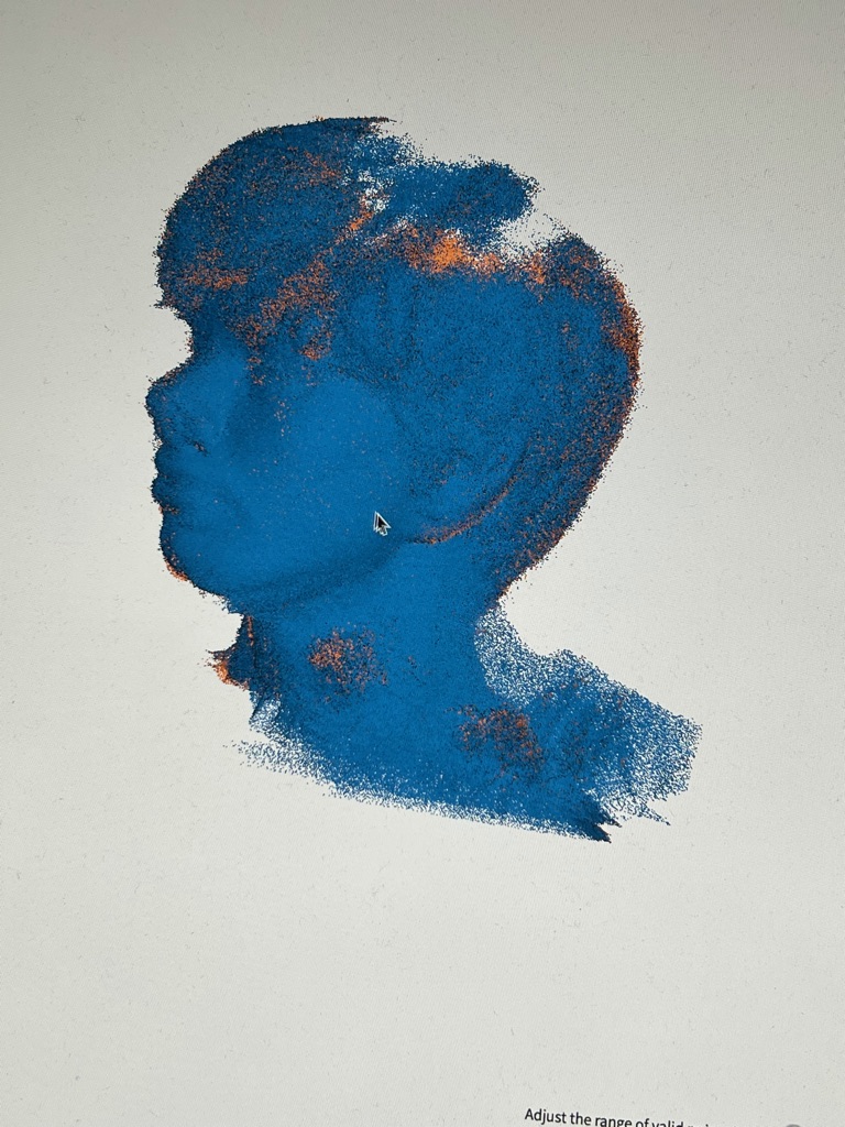
My main face traits were fairly detailed, but the camera really struggled with my hair (which makes sense honestly). After trying to scan my whole face multiple times, I gave up, as I was not willing to shave my hair to have a good result.
While I was looking through random things in the lab, I found a box filled with Lego pieces. Ever since I was a kid, I've loved Lego. Here's a short stop-motion clip I made when I was 12 years old:
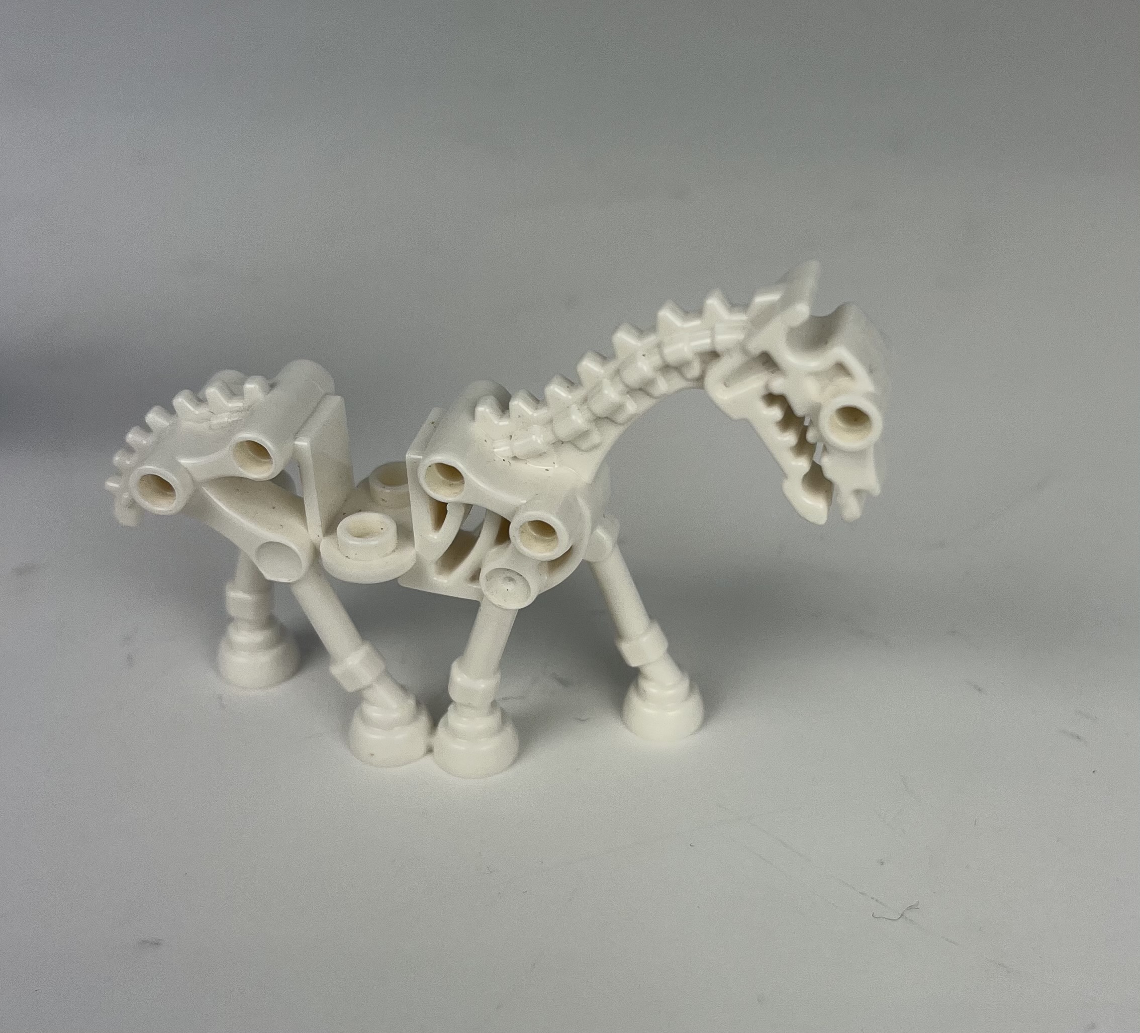
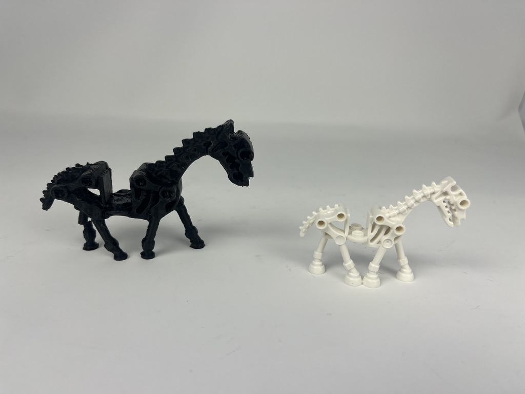
There was this really interesting skeleton Horse, which had a cool shape that would be really hard to replicate with CAD, so I decided to scan it.
There's a small rotating base in the lab that is really useful to scan objects, as it rotates them in a slow and consistent way so that the scanner can keep track of the object and at the same time get measurements from every side of it. It is possible to do it by hand, by moving the camera around the object, but I don't recommend it because the camera can very easly loose track of the object, and once that happens it's extremely hard for it to "retrack" the object. This problem happened to me more that once, and I was forced to restart the scan each time.
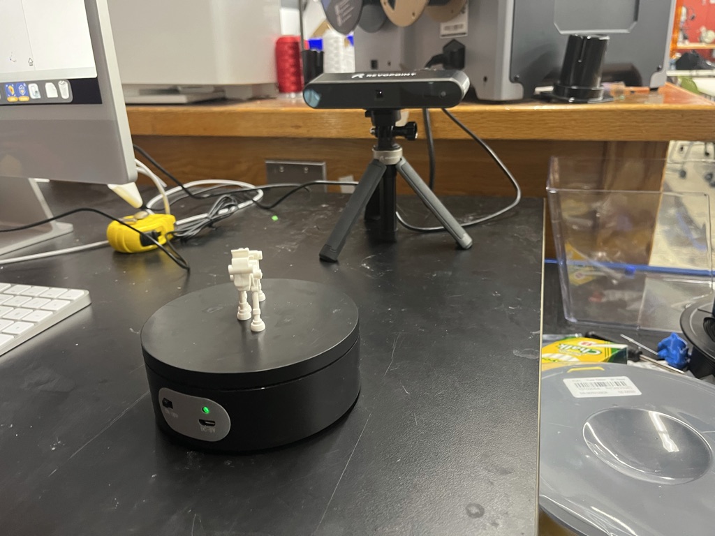
Picture of the setup I used to scan the lego horse
The result of the scan is called a cloud point, which as its name implies, is a cloud of points, and not a 3D model. The result therefore has to be processed to be converted to a 3d mesh (.stl file for example). The RevoPoint software has many options to edit the result, which I used mainly to remove small floating meshes. But other than that, the output file is ready to use to either view it in your computer, or 3D print it.
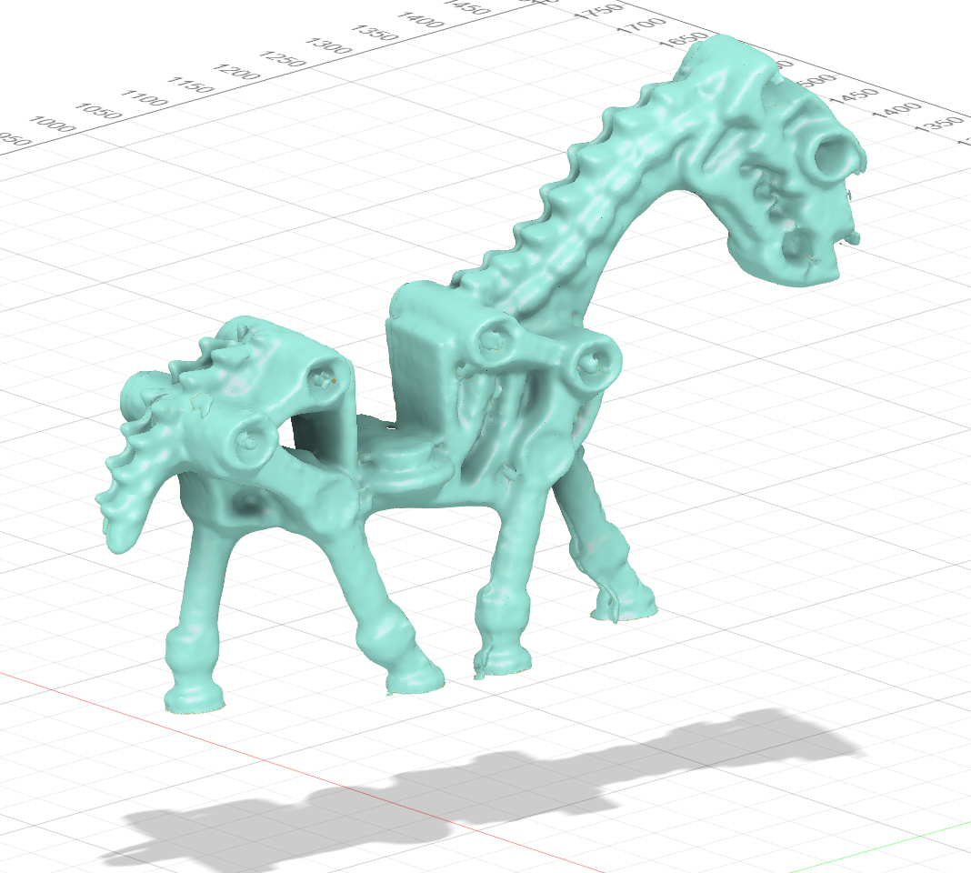
3D Model
3D Printing
The thing I was most looking forward to this week was 3D printing. This fabrication method is what I intend to use to build a big chunck of my final project. There are two main types manufacturing:
- Substractive manufacturing: raw material is cut to produce a desired shape and size
- Additive manufacturing: material is joined/deposited/solidified by (generally) a machine layer by layer, such as 3D printers
The lab has quite a few Prusa MK3 printers, which are very capable and can print medium-sized objects. Although they are not very fast, the result is definitely worth the waiting. The worflow to use them is as easy as exporting a 3D model as a mesh, "slicing" it with the help of a slicing software (such as Prusa Slicer), and sending the gcode (set of instructions) to the printer.
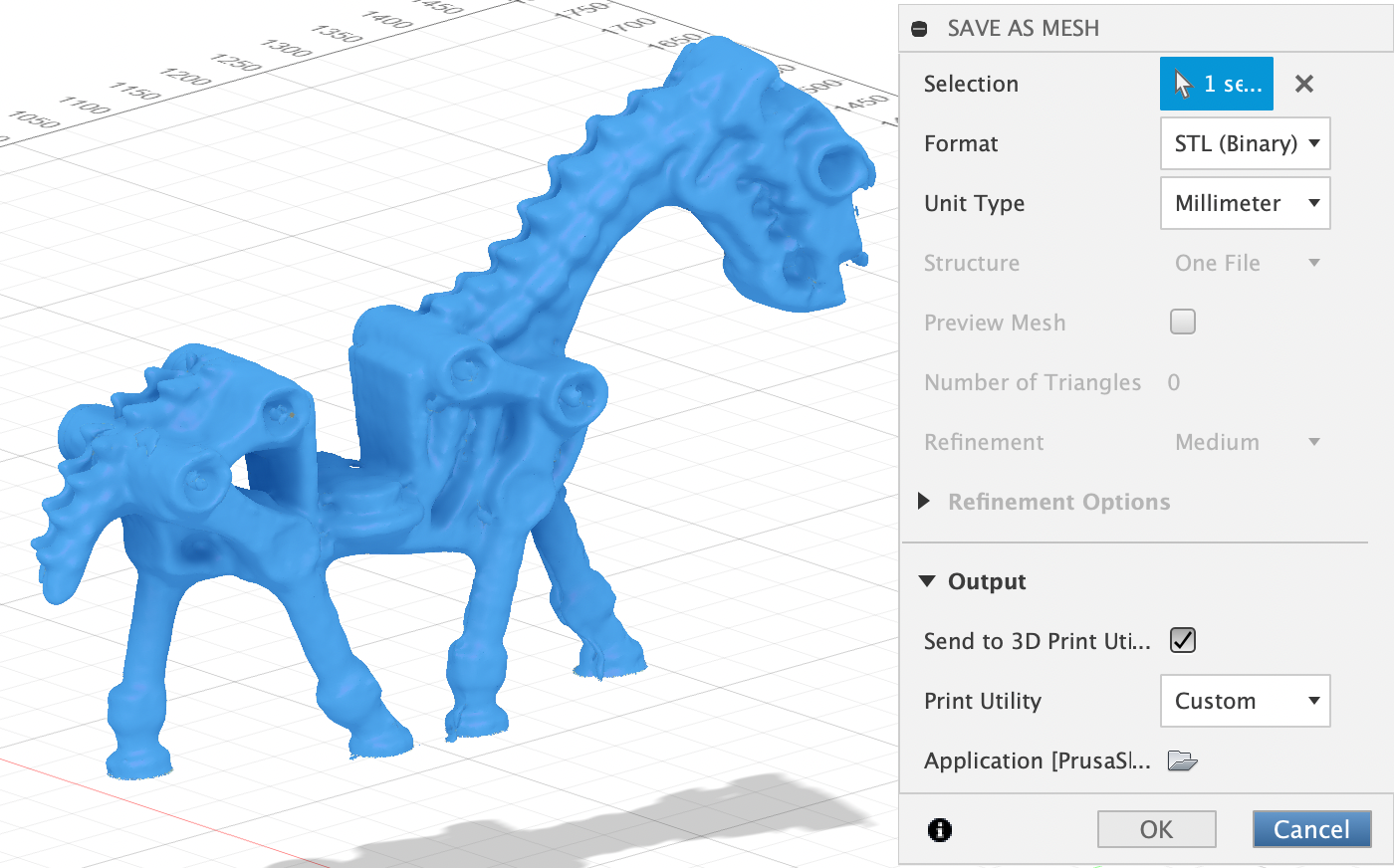
Exporting the 3D model as a mesh to the slicer
The slicer's job is to generate a file containing all the places the printer has to go, based on your 3D mesh. It therefore needs to know exactly what printer you're using, what material (PLA in my case), and a lot of other things.
Some objects have big slopes that impossible to print, because it's not possible to print in mid-air. That is what supports are for. They provide a surface for the printer to put material, and then are easly removable once the print is done (or at least they are supposed to be...).
Slicer with no supports enabled
Slicer with default supports enabled
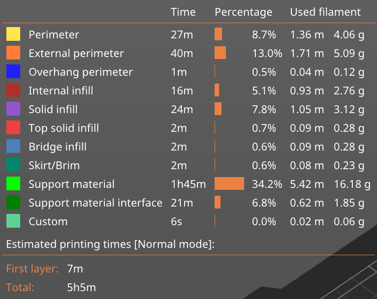
The slicer also tells you how long the print will take, and how much material it will use. You can find the time required for this print in the image below.
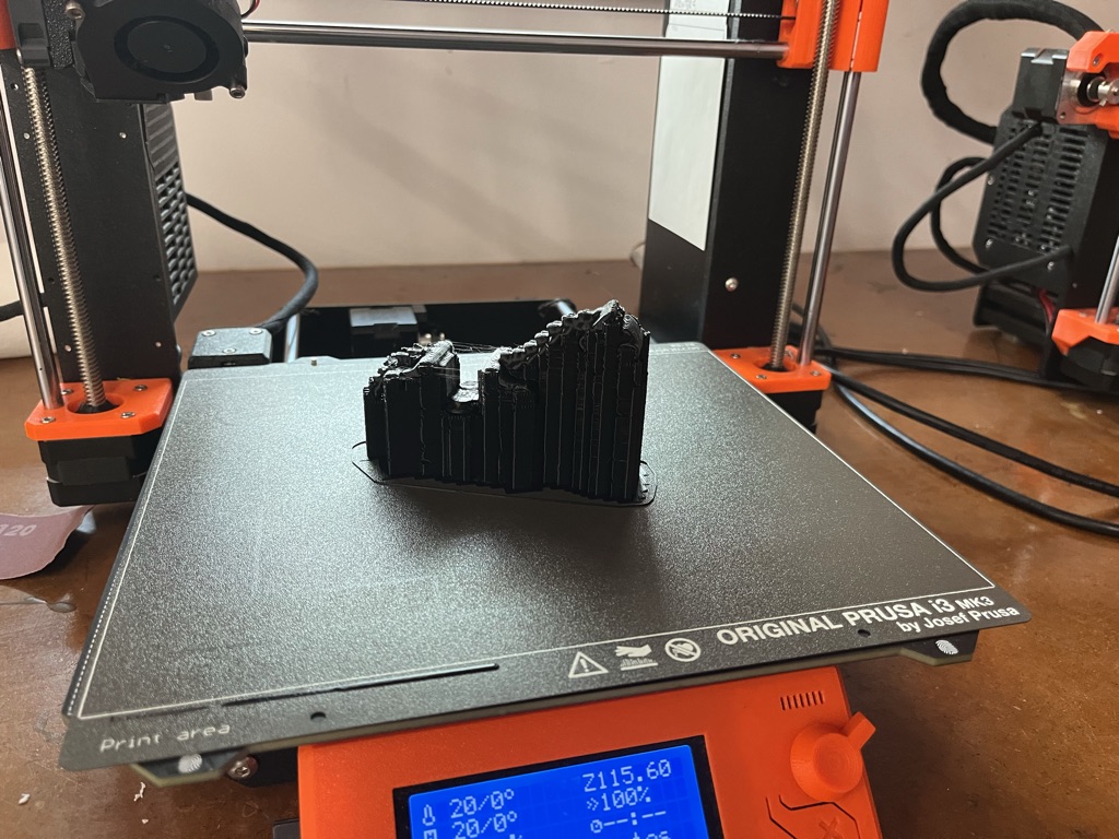
The next day I went to the lab to see the result, and found myself with a black plastic brick.
The support was extremely hard to remove. It took me more than one hour with the help of a small screw driver to get rid of it. It was so difficult to remove the support, and I had to do so much force, that two of the breaks of the horse unfortunatly broke. This first print served me as a lesson to always test different orientations when slicing the model, as I could've probably used a lot let supports if I had printed it side-ways, intead of upright. Nevertheless, the result was actually much better than I expected, but of course had some errors.
I am definitely very happy with the results, but most I importantly learned a lot of useful and interesting things, which I am sure will use in my final project.
Click here to download the .stl file and the .gcode file.