Electronics and Tools(or how to build a Mini-Fountain)
5th July 2023
Idea and objectives
This week we learned about Motors, Electronics, and Microcontrollers. To create something using all of those new concepts, I decided to create a water fountain. I knew from the begining it wasn't going to be an easy task, but I encountered a lot more problems than I initially expected.
The main challenges of this project are:
- Fabricating a watertight container
- Controlling and using a water pump
- Ataching the different parts of the project (water container, pump, electronics, etc)
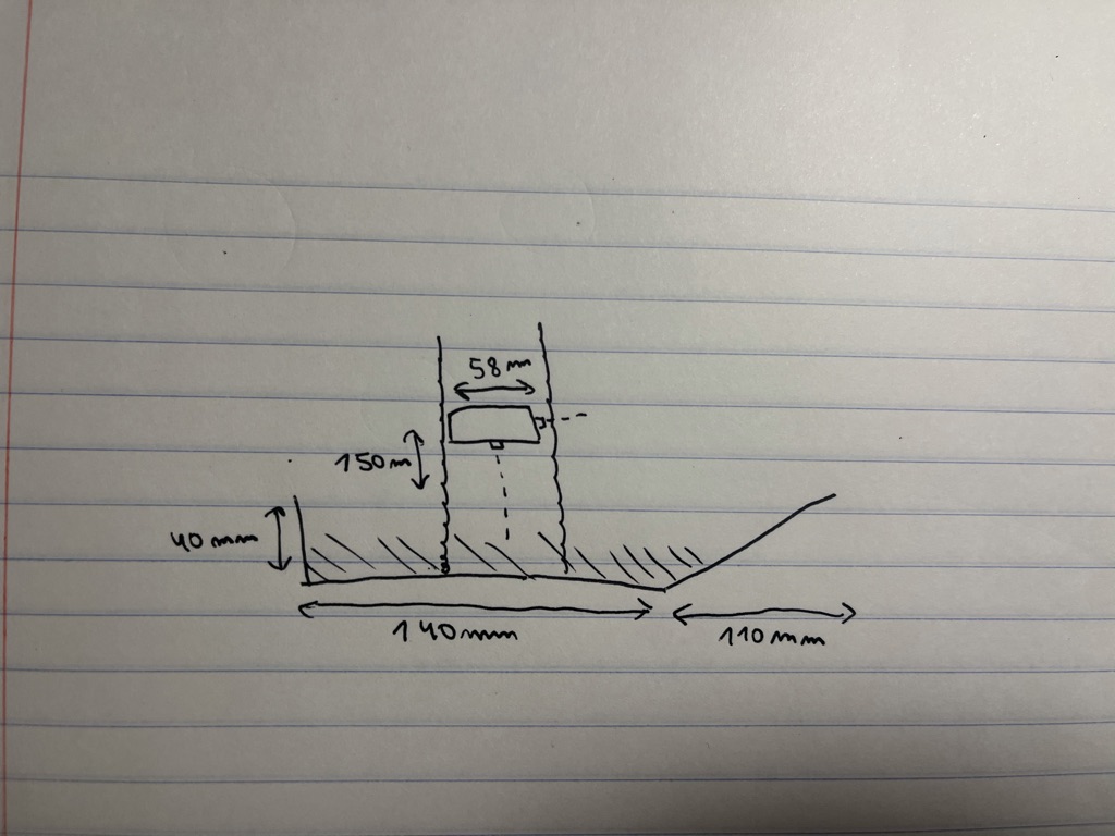
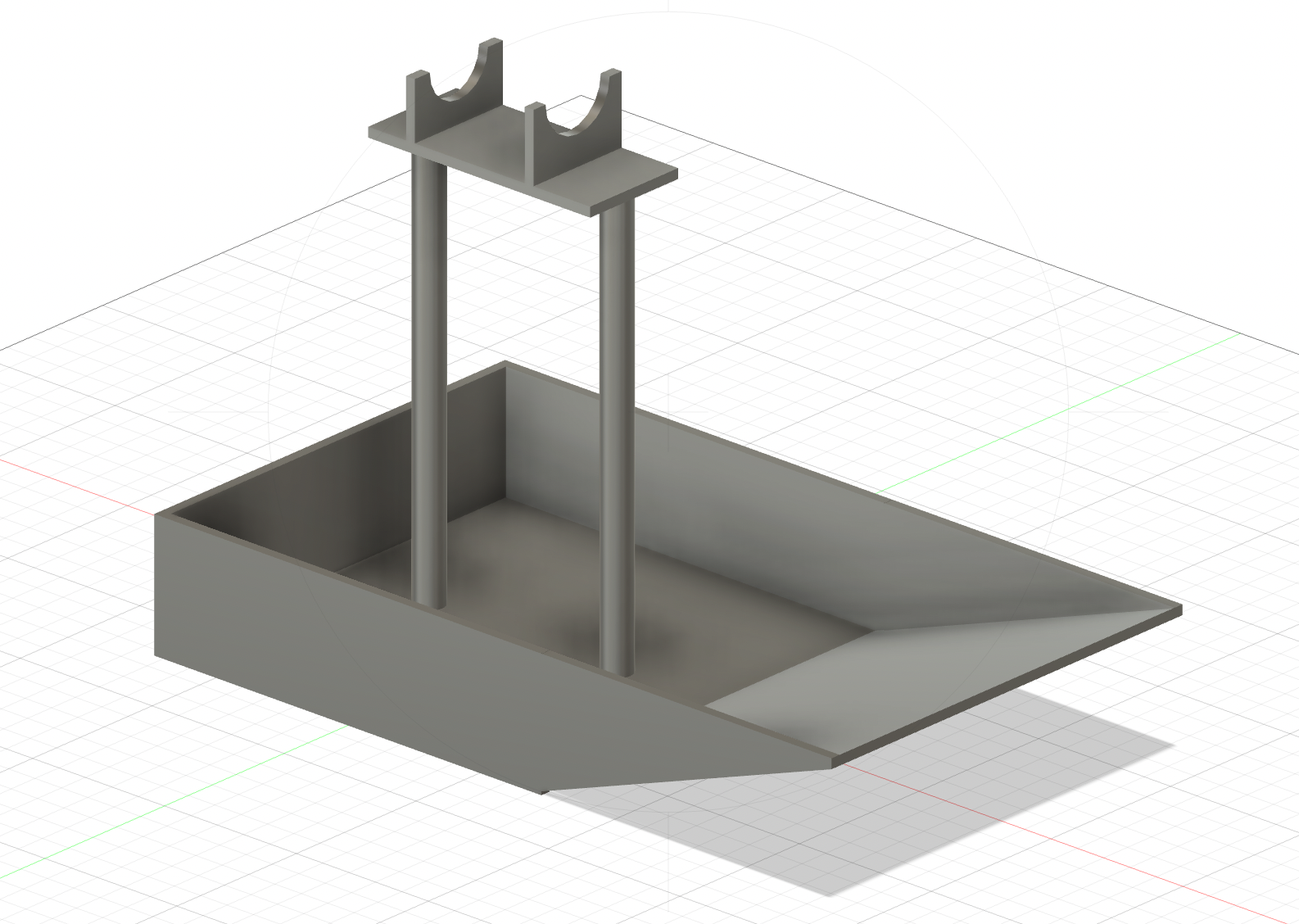
I started by drawing some sketches. I drew a boat-like shape, and a small structure on top of it which holds a small water pump (which I had found in the lab last week). I added some dimensions to have an idea of how the thing would actually look, and then modeled it with Fusion360.
Click to download the .f3d File
The main idea is to have an acrylic base (with a boat-like shape) that can serve as a water container. A secondary smaller base would hold a water pump in place, along with all the required electronics (esp32, batteries, motor driver). The two bases will be attached with two aluminum rods and M6 screws (more on that later).
Prototyping
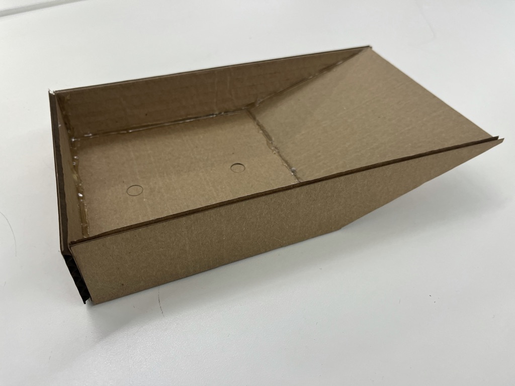
After finishing the CAD model, I laser-cutted the whole thing with cardboard to make sure everything would fit correctly, as I didn't want to waste acrylic. It was important to test if the water pump holder fitted, if the container dimension's were decent, and have a rough idea of how the fountain would look in real life.
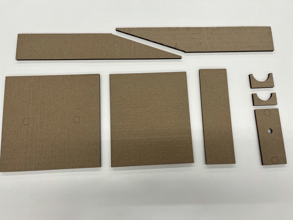
I then decided to use a highly advanced chemical compound to join all the pieces together: hot glue.
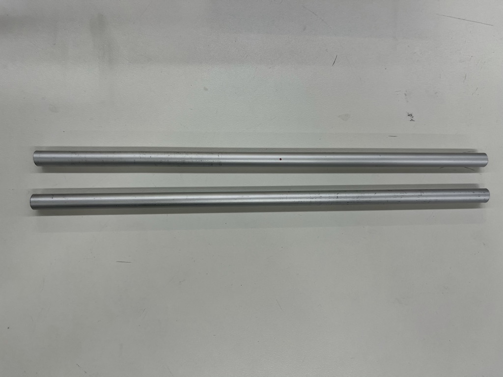
The next step was to join the two "bases". As I said earlier, we are going to use aluminum rods. The problem is that the lab only had very long aluminum rods. I therefore had to cut one in half to create two smaller ones using a hand saw.
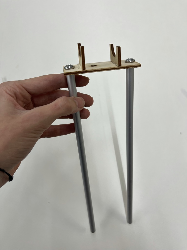
The next challenge was to figure out how to attach the rods to the top-base (which holds the water pump and the electronics). Last week we were taught how to thread the inside of a hole, and the rods I'm using happen to be hollow, so I used a M6 screw drill tip to thread the end of each aluminum rod. Finding a fitting screw was quite a challenge, and I ended up switching to the imperial system to find an appropiate screw (I basically went through every single screw in the lab to find the right one).
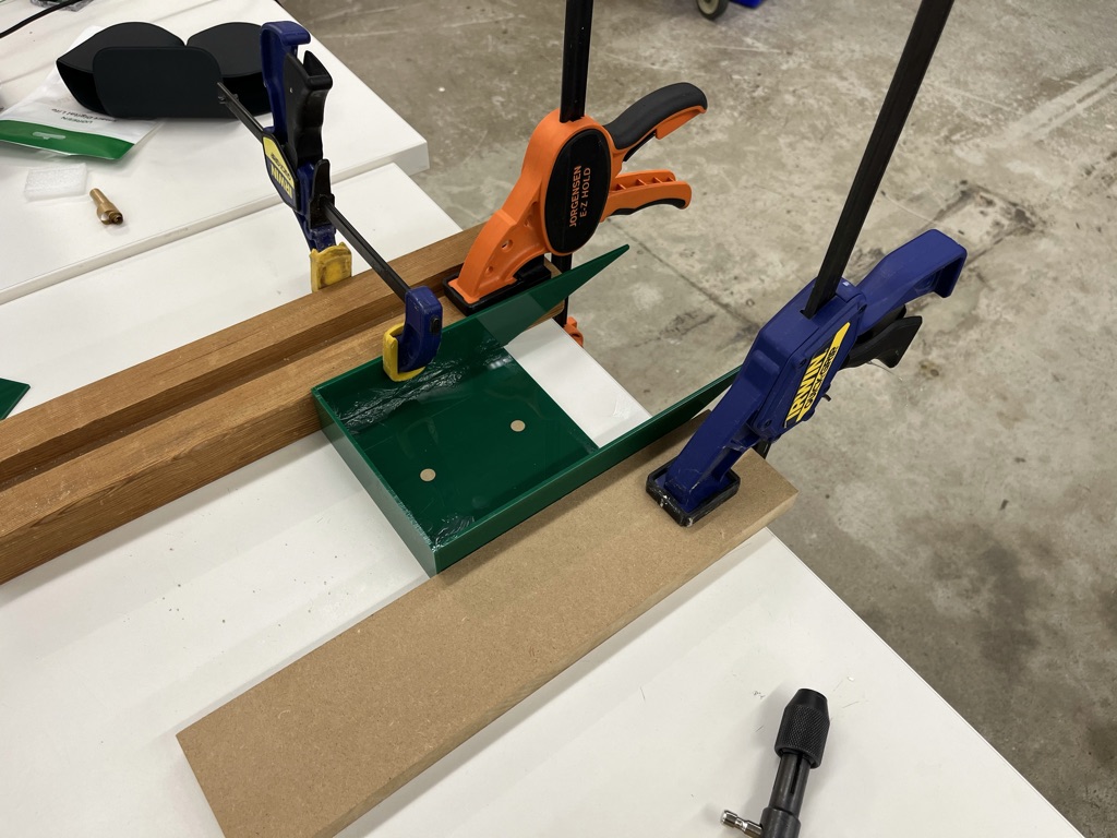
Final build
I laser-cutted the structure in acrylic, clamped it together, and glued it with epoxy. After waiting approximately 30 minutes, I glued the "ramp" to the rest of the structure, which was impossible to do before the rest of the structure was glued together.
After assembling everything, I realized that due to a pretty low contact surface, it was not going to be possible to glue the two aluminum rods to the base using epoxy. This is the kind of thing that I should've planned beforehand, but because my lack of experience, didn't think of. I ultimately decided to drill two holes through the base of the fountain (which was extremly hard to do, mainly because of clamping issues) and attach the rods using screws. After threading the inside of the rods again, which was a really tedious task, I was finally able to attach the rods. All in all, this problem was a big setback with delayed the project more than I expected.
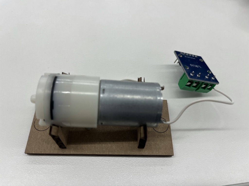
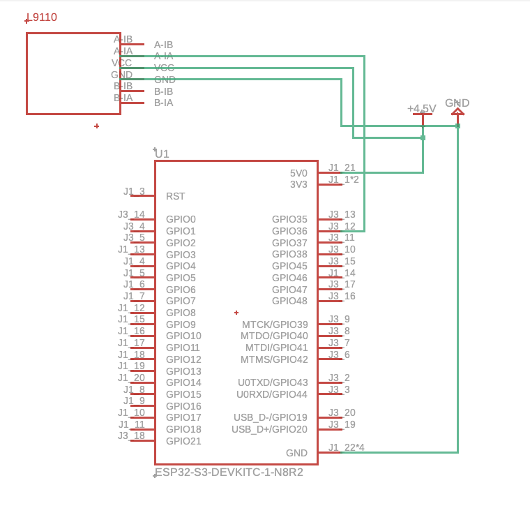
The next step is to assemble all the electronics. 3 AA batteries are connected to the 5V (4.5V in total, 1.5V each battery) and GND pins of an ESP32, aswell as the VCC and GND pins of a motor driver (I used the L9110). The ESP32 is connected to the A-IA pin of the motor driver (make sure the esp32 pin supports PWM, I used pin 12), which controls the speed of the motor. The motor driver is then connected to the water pump using two terminals and the wires that come with the motor. To easly manage power, I used solder to add two extra outputs to the batteries. This was necessary because as we just discussed, two components need both VCC and GND inputs. To keep things simple (and mainly due to a lack of time), I zip tied all the components. Before assembling the components, I quickly threw together a schematic in Eagle (fusion360) to have an idea of what the electronics would roughly look like (see image below).
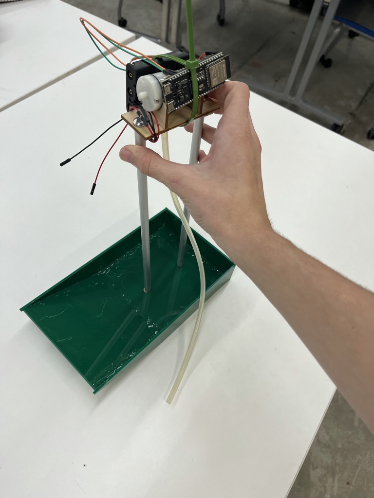
The final thing we need to do to have a working fountain, is to program our microcontroller. I will use the arduino programming language. I wrote a simple program that varies the speed of the pump over time using a sine wave, and uploaded it to the esp32 to finally test the water fountain.
#define A1A 12  // pin 12 is defined for A1A, which controls the speed of the motor

void setup() {
  pinMode(A1A, OUTPUT);
}

void loop() {
  runMotor(A1A, 180, 255);
  delay(1);
}

// Variables for calculations regarding motor speed
float value;
float interpolatedValue;

// Function that drives motor with a speed interpolated from 'min' to 'max' using a sine wave
// Inputs: pin, minimumSpeed (0-255), maximumSpeed (0-255)
void runMotor(int pin, int min, int max) {
  value = sin(millis() / 1000.0);
  interpolatedValue = map(abs(value * 100), 0, 100, min, max);
  analogWrite(pin, 255 - interpolatedValue);
}